 AC3D
Manual AC3D
Manual
AC3D
Manual AC3D
ManualAC3D is continually being developed. If you think it should be changed in any way (new features, different methods etc) then please email me. If you think there's something missing from this manual or if something could be described better then please let me know.
andy@comp.lancs.ac.uk
IMPORTANT - UNDO is not yet fully implemented! Currently it will undo the last operation that is shown on the undo button.
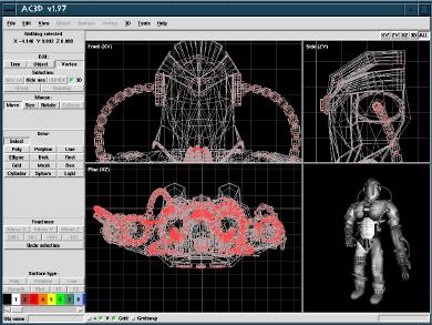
The dividers between the 4 view windows are draggable and you can select individual view by clicking on the view buttons at the top right of the main window (alternately press F1-F5 for the different views).
The main window size/position and other settings are saved when you 'save settings' (in the File menu) so the first thing you should do is to position the window where you want and select this.
There are two viewing modes accessable by pressing '1' and '2' in the
3d window (or by selecting
the menu items in the '3d' menu):
Spin mode - In 'spin' mode - rotate the view with the first mouse button, zoom in and out by pressing the 2nd mouse button and dragging the mouse vertically. Press 'w' for wirefame, 'f' for filled, 't' toggles textures. 'l' toggles the fixed light. The cursor keys can also be used to control the spin.
Walk mode - you can navigate using the cursor keys (in a similar way to 'Doom/Quake'). You must be in walkmode. '2' switches into this mode ('1' switches back to spin mode). Use up/down the cursor keys to move, left/right to turn. pressing control with the cursor keys tilts your position and alt moves you left, right, up, down. You can also control walking with the mouse - the first button turns and move forward and backward, the right button controls up/down/left/right novement.
A 3d grid is available - toggle with 'g'. the grid is always on the XZ plane (floor). The default grid square size is 1 metre and the default grid size is 20x20 squares. This can be modified by editing the prefs file.
A single light is provided. It can be switched with 'l' or by using the item in the 3D menu on the control panel. The position of the light can be altered by editing the preferences file (see later).
Selecting - The edit-mode defines the granularity of selection. In Vertex-mode you can drag a box around or click on a single vertex. In Object-mode selecting one or more vertices of an object causes the whole object to be selected. In Group-mode you can select a group of objects just by selecting part of a single object. As a shortcut, the mouse buttons can be used instead - the left button moves, middle (if your mouse has one) resizes, right button rotates. You'll probably find that you only ever need to press the Extrude button in the mouse section.
If you are setting surface colour or performing operations on surfaces then only those sufaces that have every vertex selected will be altered.
Resizing - select the handles in the corners of the bounding box to resize the selection. On the edge handles, hold the control key down whilst moving the mouse to resize opposite edges. The control key currently has no effect on the corner handles. Note that it's possible to resize a selection down to zero width. This is useful for lining up vertices.
Moving - if you drag the green box you can reposition the selection.
Holding the control key down whilst dragging lets you constrain movement
to up-down ot left-right only.
To unselect everything, Edit->select-nothing or click the mouse outside
the bounding box.
Extending/Negating the selection - Press shift whilst selecting to extend the selection and press shift whilst selecting with 2nd (or 3rd) mouse button to negate the current selection.
Extended and negate selection work in all select modes e.g you can add/subtract whole objects from the selection when in object mode.
Selecting in the 3D window
- recent versions of AC3D allow you to select objects from the 3D window.
Hold the control key down and click on an object to select it. This
also works in a similar way to selection from the 2D windows - you can
extend or negate the selection in the same way.
Extruding - extruding works on objects so you need to be in 'group' or 'object' edit mode. You should note that 2D shapes (lines, polys) extrude best, and that extruding 3D objects can result in many unnecessary surfaces from being generated (usually hidden inside the object somewhere) Select the object to be extruded, select extrude then drag the object in the direction you want to extrude it. You can change the extrude subdivisions from the settings dialog. TIP - if you hold the Control key down then your drag is constrained to the direction you first move in - this is usful for extruding at right angles.
Hiding objects - this allows you to temporarily remove objects from the views and means that you can work on much larger models. You can hide selected objects and hide objects that are not selected. Press 'unhide' to show all objects. The '3d' toggle determins if the hidden objects are visible in the 3d window.
If you select two vertices, the distance between them will be displayed in the control panel.
 |

POLYGON, POLYLINE, LINE in 3D window |
Surface type can easily be changed by selecting some surfaces and pressing the Surface-type button which is near the bottom of the control panel:
![]()
This panel also contains controls to set surfaces to be smooth or flat. This determines the way that a polygon is drawn (it has no effect on lines or polylines):
If a surface is flat-shaded, the colour across the surface will be constant. If it's shaded then the colour will be 'graded' depending on lighing conditions.
If some surfaces are next to each other, and the vertices are shared (i.e. one or more surfaces use the same vertex), the effect will be of one continuous 'smooth' surface. The vertices must be shared for two surfaces to be smoothed together. This shading is a good way to make smooth looking objects from relatively simple shapes.
The '1S' and '2S' buttons select how many sides a surface has. (one sided or two sided). If a surface is single sided then it will only be visible from one side. The following pictures aims to demonstate this:
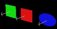
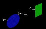
In this simple model there are three objects - a green rectangle, a red rectangle and a blue ellipse(made by creating an ellipse object and setting it's surface type to be POLY). The red rectangle has been set to be single-sided '1S'. This means that it's visible from it's 'front' but not from the back (the second image shows the whole model rotated). Objects such as spheres and cubes, which don't have any interior surfaces visible, benefit from a speed optimization when being drawn with the surfaces single-sided.
The direction a surface is facing is determined by it's 'Normal' (indicated by arrows in the above diagram). This is a 3D graphics term for a line at right angles to the surface that indicates a direction. Normals are used in the renderer's lighting calculations. To flip a single-sided surface, use Surface->Flip normal. (This actually reverses the order of the vertices in the surface so that the automatically generated normal faces the opposite way).
Note that normals are not displayed by AC3D.
Resetting views - Press 'space' in an orthographic window to center all windows about the origin and reset the zoom levels.
Viewing the selection - Press 'f' to fit the current selection into the current window. 'F' fits the selection to all windows. Control-F fits the whole model into all views. Use 'g' to 'goto' the current selection - the window will centre about the centre of the selection. 'G' centres all windows. These options are also in the View menu.
Three functions available from the View menu allow you to centre the 3D view about the selection, the cursor (that's positioned with ALT-click in the 2D windows), and reset to view the origin.
Dragging in a window allows you to specify two of the dimensions for the new object - the third is specified from the 3D cursor. You can move this by holding ALT down and dragging the cross around with the mouse. This specifies the missing position. Most people never use this because it's easy enough to create an object and position it where you want.
Changing the number of subdivisions (in the settings dialog) alters the way circles and spheres are drawn (and the way objects are revolved - object-menu) Spheres have n*n*2 surfaces in them so beware. You can also change the mesh dimensisons - meshs can use many surfaces too (x*y*2)!. Spheres and Meshes can be made from triangles or quads (alter settings).
You should make them from triangles if you intend more pull the vertices about, oterwise you may have non-planar rectangles which can cause problems with some renderers and raytracers.
Polys/polylines/lines - When drawing a poly/polyline/line, click to position each point and either double-click or press mouse button 2 or 3 to end. You can alter the surface type later from the control panel if you want a different type. If a polygon shows as a red outline in the 3D window then it means that there may be edges overlapping (you will need to move some vertices) OR two or more vertices sharing the same location (you can fix this by selecting Object->Optimize vertices). It is actually possible to draw a line or poly in different windows - creating a non planar object. This is fine with lines but is not correct for a polygon which should have all it's points on the same plane.
Experiment with these objects to see what is available. Objects can be named - these names are used when generating output files. If you are generating VRML or Dive files, you can associate URLs with selected objects by entering text into the field on the Tools->Object Data window.
Note that there is no cone object. You can easily make one in a number of ways. Create a cylinder, select one end (in vertex mode) and press 'snap together'. A cone made this way will have the texture coordinates set correctly. For a simpler cone (less vertices), no texture map) you can optimize the vertices. This means that the cone's point will be one vertex which is shared with all the sides (texture mapping this object wil not give satisfactory results. Some other ways of making cones are - make a 'disk' and pull the centre point up; revolve a line around an axis. If you want a base on the cone then - select the bottom vertices and select 'Vertex->Create surface/object'.
Note that at the moment, there is no way to adjust type, colour, brightness of lights. You can only select and move lights in Group or Object select mode.
Lights are generated in RIB files and POV files. You can edit their attributes in the generated files.
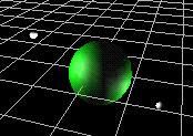 This image shows
a green sphere with two lights (indicated by white spheres) - the main
headlight is turned off. The main headlight in the 3D window is toggled
on and off with the 'l' key (or from the 3D menu). If this light is on
when POV or RIB files are generated then a light will be added to the file.
This image shows
a green sphere with two lights (indicated by white spheres) - the main
headlight is turned off. The main headlight in the 3D window is toggled
on and off with the 'l' key (or from the 3D menu). If this light is on
when POV or RIB files are generated then a light will be added to the file.
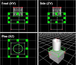
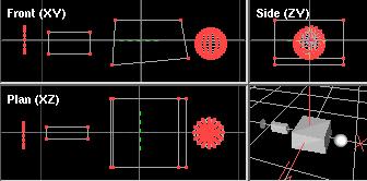
To extrude objects:
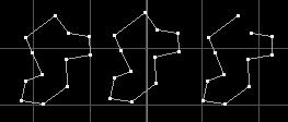
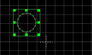
| Select one or more objects to be extruded This picture shows a polygon drawn in the side (XY) window. | 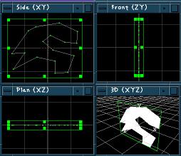 |
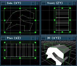 |
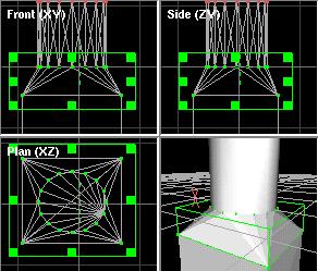
Press the 'Extrude' button. Drag the bounding box in the direction you want to extrude. In this case, the selection in the plan (XZ) view was dragged downwards. |
You can alter the number of segments that will be created in the extrude. This determines the number of divisions in the distance you drag for the extrude. Select File->Edit settings to change this.

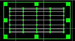
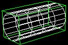
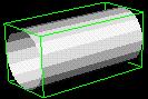

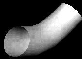
In this example, a Ellipse is created and extruded after setting "Extrude segments" to 4. Notice how there are now 4 sections to the object. The object is set to be smooth shaded by pressing the "SM" button on the control panel. The section vertices can be selected and moved/rotated, in this case making a pipe.
If you extrude a polygon then that polygon is dupicated for the end. For example - if you extrude a rectangle, the new 'end' of the box will be a copy of the original polygon. If this is single sided then it will probably not be visible. You may need to select the new end surface (in vertex mode) and select Surface->Flip normals to reverse it.
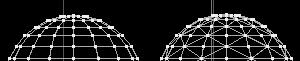
To create a torus -make a circle in the Side window:
Select 'Object->Revolve Y'
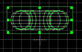
You should see something like this:
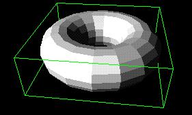
Select the 'smooth' surface type (naer the bottom of the control panel) to make it appear rounded

Change the num-surfaces-divisions in settings to change the resolution of the revolve.You can also change the degrees of revolution 1-360 degrees.
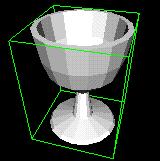
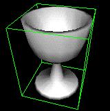
If you have points that you want to be in the centre of the final revolved object - (e.g. the start and end points of the cup profile above ) then you should ensure that these points lie exactly on the axis. You can do this by either drawing the line with 'gridsnap' on or by snapping those points to the grid or by using Move-to and ensuring that two of the values are zero. If these points are not exactly on the axis then you'll get a small hole or possibly overlapping surfaces (you can always use the 'snap together' function and optimize vertices or remove duplicate points later though).
Optimize Vertices - removes duplicate vertices from each selected object. For vertices to be removed, an object must own the vertices and they much match the same position exactly. The function will share one vertex between each connected point. This means that vertex normals can be calculated if smooth shading is needed. It also removes duplicate vertex references from the surface - something which might cause a bad polygon.
Optimize Surfaces - attempts to remove any duplicate surfaces and any polygons that consist of 1 or 2 vertices (you may have these if you have deleted vertices from an object).
Re-centre If you have object centres visible ('+' at the bottom of the control panel) then you can re-center this point about the objects center of gravity. This can be useful for specifying where the pivot points or local-origin of an object are.
Minimum-centre -This function sets the object's origin to the minimum xyz of the object. It is used to create AC3D fonts for the Tools->Add-Text function.
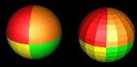
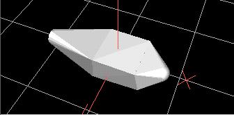
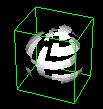 Fragment
- make a selected object into many objects - one object per surface
of the original object. This is useful if you want to pull and object to
bits or for texturing each surface with a different picture. This image
show a sphere that has been fragmented and surfaces have been moved. Notice
that the surfaces are no longer 'smoothed' together - this is because each
surface is now a separate object and vertices cannot be shared across objects.
Fragment
- make a selected object into many objects - one object per surface
of the original object. This is useful if you want to pull and object to
bits or for texturing each surface with a different picture. This image
show a sphere that has been fragmented and surfaces have been moved. Notice
that the surfaces are no longer 'smoothed' together - this is because each
surface is now a separate object and vertices cannot be shared across objects.
Merge - merge all the surfaces selected objects
into one single object. This does NOT optimise the vertices so that they
are shared. (You might want to select 'optimise vertices after merging
if you want a more efficient object and/or smooth shading across adjacent
surfaces)
Explode - similar to fragment, you enter
a distance and each surface in the select object is moved by this amount.
Flip normal - this effectively changes the direction of the vertices in each selected surface. This reverses the way that a poly 'faces'. A polygon is defined as 'facing' if the vertices appear anti-clockwise to the viewer. If a polygon is set to be one-sided (by pressing the '1S' button on the control panel) then it will only be viewable from one direction - the direction it is facing.
Change vertex order - this changes the order that the vertices are drawn in a surface by moving the first vertex to the end of the list. You can use this to change where the break in a line is. This can also be used to fix bad polygon which has the first three vertices in a non anti-clockwise order - causing the normal (used for lighting) to be incorectly calculated.
Subdivide surfaces - only works on triangles and quads. Makes 1 triangle into 3 surfaces (new vertex at centre). Splits quad into four smaller quads.
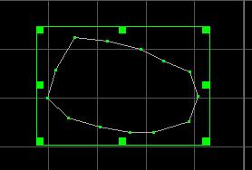
Spline surfaces - Useful for smoothing out a 'line' object and for rounding off polygons. New points are interpolated between existing points.
Spike - creates a 'spike' in place of each quad or triangle selected. The 'spike_factor' can be altered by editing the 'spike size' in the settings window - this defines the distance that the apex of the spike will be away from the original surface.
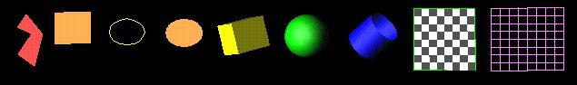
Make hole - adjust hole% on settings window to alter size. Can actually be used with more than 100% - this just builds new surfaces out rather than in from the edge. Some concave polygons may have overlapping surfaces after making holes - you might need to move some of the vertices about.

This image shows 4 objects that have had holes made in them - An Ellipse (set to poly surface-type), a sphere, a cube and a disk. Notice how you can't see the inside of the sphere or cube through the holes- this is because the default surfaces for these objects are single-sided and face outwards. To see the insides though the holes, you'd need to select these objects and press '2S' on the control panel.
Using values > 100% can make 3d objects go weird! This can be used to extrude a single surface (make hole and select/drag the new points).
Bevel - creates another surface which is smaller than the original, moved away slightly and joined by new surfaces around the edge. The original surface is discarded. The distance the new surface is moved and indented is specified in Settings (Bevel size). Beveling a concave polygon can result in new points being positioned incorrectly you may need to move these. Beveling can be used to extrude single surfaces. This may be easier than trying to assemble two objects together. e.g. bevel a surface, selected the new surface (in vertex mode) and drag it.
Triangulate - splits a surface into
triangles. The operation can fail if it is given a 'bad' polygon - i.e.
one that has
overlapping edges or duplicate vertices.
Some surfaces in file formats generated by AC3D are automatically triangulated
(if they need to be) - some are not though.
Renderers that can't cope with concave polygons may give odd results
if they are given them.
 Cut
away object - takes all selected surfaces and vertices and puts them
in a new object. This can be useful for extracting parts of objects. e.g.
splitting a sphere into two.
Cut
away object - takes all selected surfaces and vertices and puts them
in a new object. This can be useful for extracting parts of objects. e.g.
splitting a sphere into two.
Remap-texture-coors - see texturing section.
Snap-together - this sets all selected vertices to the same location. The vertices can be in separate objects or the same object. The point that they are snapped to is the average of each point.
Snap-to-grid - moves each selected vertex to the nearest grid position. This may or may not be the visible grid. The snap grid is defined by 'snap grid' in settings and may be different to the 'draw grid' which is the visible grid.
Snap-objects-by-vertices
- this is for aligning two objects. You must select one vertex in each
of two separate objects. The objects will be aligned by shifting the objects
together so that the vertices are in the same place.
Snap-object_vertex_pairs
- this looks at vertices that are selected in two different objects and
snaps adjacent pairs together. This is useful for joining the ends
of two objects together,
 Insert
Vertex - inserts a new vertex between each selected pair of vertices.
If you insert a vertex between two vertices of connected surfaces then
two different vertices will be made. If you want these to become the same
point then you should select the object and choose Object->Optimize vertices.
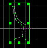
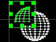
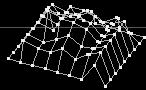
Insert-vertex is usefule for adding extra points into a line. An example
is to create a grid object (which is made from lines) in a power of 2 dimension
e.g. 8. Press 'Insert vertex' 3 times (2^3=8). You should now have a grid
where you can lift each point and create a 3d graph.
Insert
Vertex - inserts a new vertex between each selected pair of vertices.
If you insert a vertex between two vertices of connected surfaces then
two different vertices will be made. If you want these to become the same
point then you should select the object and choose Object->Optimize vertices.
Insert-vertex is usefule for adding extra points into a line. An example
is to create a grid object (which is made from lines) in a power of 2 dimension
e.g. 8. Press 'Insert vertex' 3 times (2^3=8). You should now have a grid
where you can lift each point and create a 3d graph.
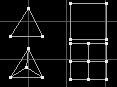
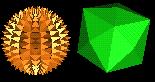
Create surface/object - this
uses a complex technique called 'convex hull' to create a new object that
surrounds the vertices that are selected. This is very useful for
joining complex objects together or for simplifying the creation of some
complex shapes.
These two pictures show the function being used to join a cylinder
to a cube. The new object will always be flat shaded but you can
set it to smooth by pressing the "sm" button on the control panel.
Note that because this function makes a new object, the vertices are not
shared with the old objects. If you want to make the whole shape
smooth then you need to merge all the objects together (object->merge)
and then optimize the vertices (object->optimize-vertices)
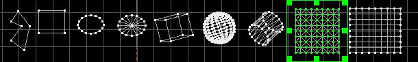
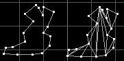
This second example shows 4 objects which are 'shrink-wrapped' by this
function. The original objects still remain
inside the new surrounding one - you'll probably want to drag the new
object away and delete the original objects.
Note that the box that it second from the left is not used to make
the new object - this is because it's inside the
'wrapping area'.
Create ordered surface - select individual vertices and create a surface between them. You should select them in order and anticlockwise (to get the normal facing towards you). You may not need to use this function very often. If you need to create your own polygons then it's better to draw 'poly' objects. This function works by creating a new surface and adding vertices IN THE ORDER THEY WERE SELECTED. If you select many vertices and they are not selected the the exactly correct order then a bad surface (crossing edges) may be created.
Remove surface only - remove any WHOLE surfaces selected - vertices will remain.
Size-to - allows you to specify a size for the bounding box (selection) to be. Any objects/vertice will be scaled to fit in this box.
Move-to - you can centre the selection around any 3D point by using this dialog. The dialog is initially filled-out with the current selections centre.
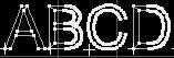 Making your own
fonts - A file for use with Add Text is just an AC3D file with named
objects - the only special thing that you need to do is to ensure that
the objects have their centres minimized (set using the Object->Minimum
centre function). To view object-centres you need to ensure that the '+'
button is on (at the bottom of the control panel). This point is used when
lining up text objects. The point is taken as the start of the 'character'
and the width of the object is measured so that the next character can
be placed the correct distance along the line, without overlapping. The
font file should be designed to be viewed from the front in the XY window,
since these coordinates are used for positioning the font objects.
Making your own
fonts - A file for use with Add Text is just an AC3D file with named
objects - the only special thing that you need to do is to ensure that
the objects have their centres minimized (set using the Object->Minimum
centre function). To view object-centres you need to ensure that the '+'
button is on (at the bottom of the control panel). This point is used when
lining up text objects. The point is taken as the start of the 'character'
and the width of the object is measured so that the next character can
be placed the correct distance along the line, without overlapping. The
font file should be designed to be viewed from the front in the XY window,
since these coordinates are used for positioning the font objects.
You may find the Add text function useful for storing a library of objects e.g. furniture. Although, each object can only be indexed by a single character.
If you want to extrude a polygon based text font - you may need to select the newly created end surfaces and select 'Surface->flip-normal' to make the polygons fully viewable.
To create accurate 3D text objects from TrueType fonts (as used by Windows
etc)- use Font3D to generate DXF files and import them into AC3D.
Font 3D is free to download from http://www-personal.ksu.edu/~squid/font3d.html
Registered users benefit from a special Font3D plugin.
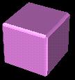
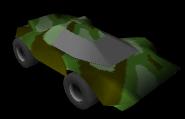 Each object can
have one texture - set from the object->texture menu.There are default
texture mappings set for the primitive objects when they are created but
you might need to remap the texture coordinates.This is done by axis (Object/Surface->remap
texture coors). Currently the only texture mappings are by axis.
To map at an angle, you need to rotate the object and then select remap-texture-coors.
You can also modify the texture repeating for an object from the menu in
Object->Texture->set texture repeat.
Each object can
have one texture - set from the object->texture menu.There are default
texture mappings set for the primitive objects when they are created but
you might need to remap the texture coordinates.This is done by axis (Object/Surface->remap
texture coors). Currently the only texture mappings are by axis.
To map at an angle, you need to rotate the object and then select remap-texture-coors.
You can also modify the texture repeating for an object from the menu in
Object->Texture->set texture repeat.
Surface->remap-texture-coors remaps the selected surfaces. It
works by axis and finds the bounding rectangle of the selection and uses
this for the edge of the texture mapping.
If you want to have more than one texture on an object (e.g. a different image on each side of a cube) then you should fragment the object (or use Surface->cut away object) and map a texture on to each of the subobjects created.
Texture files should be IRIS RGB format (XV can save this). Windows
users can also use BMP files as textures. Registered users with a
full version of AC3D get a number of plugins that enable other image formats
to be used as textures.
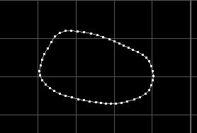
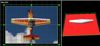
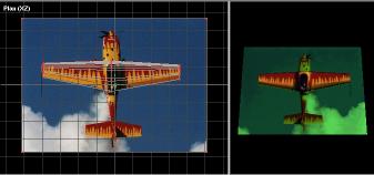
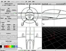 Each of
the orthographic (2D) windows can display a background image. This
can be very useful for tracing shapes or laying out objects in relation
to some scanned image e.g. a map. Background images are set and unset
from the View menu. All the image formats that are supported
by AC3D's
Each of
the orthographic (2D) windows can display a background image. This
can be very useful for tracing shapes or laying out objects in relation
to some scanned image e.g. a map. Background images are set and unset
from the View menu. All the image formats that are supported
by AC3D's
The draw grid is purely for visual guides in the orthographic windows.
The snap grid (if on) will snap moving/resizing/creating mouse movements to an invisible grid.
Both grids don't need to be set the same but they can be.
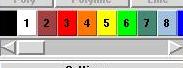 The scrolling window
of buttons near the bottom of the control panel represents the colours/materials
available for setting on you models. The default colour for an object is
palette entry 1 (usually white)
The scrolling window
of buttons near the bottom of the control panel represents the colours/materials
available for setting on you models. The default colour for an object is
palette entry 1 (usually white)
Press a button to select a colour for the selected objects/surfaces. For a surface to change colour it must have all it's vertices selected.
You can affect the overall look of a texture you alter the colour of a surface which is textured (the colour will 'show through' the texture) If you want the texture to appear as the original coloured image then the surface colour should be white.
 Editing Palette
entries - Get a menu on each button by pressing the 3rd mouse button.
From here you can edit a colour or add a new one (a copy of the selected
one will be added to the end of the list). Note that the colour on the
palette button represents the diffuse RGB values for that material. It's
quite possible to get the rendered colour looking something totally different
from that by setting other material parameters.
Editing Palette
entries - Get a menu on each button by pressing the 3rd mouse button.
From here you can edit a colour or add a new one (a copy of the selected
one will be added to the end of the list). Note that the colour on the
palette button represents the diffuse RGB values for that material. It's
quite possible to get the rendered colour looking something totally different
from that by setting other material parameters.
If you save a model with different colours/materials then palette buttons will be appended to the list when it's loaded in the future.
Transparency is suported in the palette but it's not handled correctly in the renderer so transparent surfaces may look odd.
Loading a file does not clear the current model - this allows you to have a 'library' of useful objects and load them in when you want.
Importing other formats
See the File->Import menu for a list of file types you can import. Some import/exports are disabled in the shareware version of AC3D.
Full registered versions of AC3D come with a number of Import/Export plugins that handle more file formats.
Triangle files - the format of triangle file is: each line contains 9 floating point numbers and one hex value e.g.: 0.0 0.0 0.0 1.0 0.0 0.0 1.0 1.0 0.0 0xffffff represents 3 vertices of a triangle. hex value is 0xRRGGBB col - in this case white duplicate vertices are aggregated when loaded.
The simple format of triangle files might allow you to import models from other formats more easily than converting them to DXF or something else.
Vector files - another simple format for importing 2D vector data. Each line should consist of a number of vertices followed by that many x/y coordinate pairs e.g.
3 0.5 0.5 2.5 2.5 10 5This represents a line with 3 vertices (0.5, 0.5)(2.5, 2.5)(10, 5)
VRML 1- URLs are used so that objects will be selectable in the appropriate browser. You can switch output of normals and textures in the settings window.
VRML 2 - This is an initial version of VRML2 output. Materials are not present in the file, only colours. This is due to a backwards step in the design of VRML2 - you can only index colours, not materials. URLs (entered in Dive object data) are ignored. Output of normals and textures is swtchable via Settings. Note that texture files are supposed to be a different format in VRML2. They were RGB in VRML1 but this has been changed. Unless your VRML2 browser can use RGB files, you'll need to change the format of the pictures files (using XV or similar) and edit the VRML file to modify the pointer to the picture file (e.g. texture.rgb -> texture.jpg).
DIVE - Dive files will handle textures. The Dive generation will include the dive data (if you have input any) this is usually TCL code. If an object has a URL then the object will be a dive gateway. See www.sics.se/dive for more info about the Dive VR system.
MASSIVE - Massive is a distributed VR tele-conferencing system written by Chris Greenhalgh at Nottingham University in the UK. It runs on SGI and Sun platforms. For more details, see: http://www.crg.cs.nott.ac.uk/~csm/massive.html
RENDERMAN - files for raytracer. See http://www.seas.gwu.edu/student/gritz/bmrt.html for a good rendering tool (BMRT) and other pointers to Renderman related stuff. The eye viewpoint is defined by your view position in the 3D window (approx). Note that lines don't make sense in a raytracer and will not be output. If you get any polygons with one or two vertices only, you may get a bad-polygon message. If you want to clean these away use 'Object->optimize surfaces'. Textures from picture files are not supported although there may be a way that this can be accomplished by using a custom shader - see the URL above for more details. Any polygons that need triangulating (breaking up into triangles) will be triangulated.
POVRAY - Ray tracer see www.povray.org for more info. The eye viewpoint is defined by your view position in the 3D window (approx). The colour palette is output at the top of the file (each entry has the same number as the AC3D material). The properties can be altered easily to provide different surface types and textures (you might need to add some #includes to get external definitions). The light is output at the end of the file. The lights position is the same as the viewers. The POVRay output is based on triangles - lines will be ignored and polygons with > 3 vertices will be triangulated automatically. Povray does not yet support UV textures via picture files but the POV group are supposed to be working on this.
Triangle files - see loading triangle files for a description of this format. This format is very simple and is easy to parse.
The command is actually a TCL string. TCL commands are separated by ';'. by default, AC3D is configured to generate a POV file, then execute povray. An example command for POV is:
ac3d write_POV /tmp/ac3dpovfile.pov ; ac3d execute {povray +D +I/tmp/ac3dpovfile.pov &}
and for BMRT:
ac3d write_rib /tmp/ac3dribfile.rib ; ac3d execute { rendrib -d /tmp/ac3dribfile.rib &}
The first part sends a message to AC3D to write a POV file in /tmp. The
second part sends a message to AC3D to execute the povray program. This
will only work if povray is somewhere on the default search path - you
might need to specify a full pathname to the binary program. The execute
command must be surrounded by {} NOT quotes (").
Under WINDOWS it's slightly different :
ac3d write_POV ac3dpovfile.pov ; ac3d execute {"C:\Program Files\POV-Ray
for Windows\bin\pvengine.exe" /RENDER ac3dpovfile.pov }
For other renderers - the other AC3D write_ commands are:
write_dive
write_vrml
write_massive
write_rib
write_POV
| In orthographic (2D) windows: | |
|---|---|
| Key | Function |
| Cursor-keys | move view |
| Shift-Cursor | move view faster |
| Backspace/Delete | delete current selection |
| Space | home windows to origin and reset zoom in each window |
| Control-up | zoom in |
| Control-down | zoom out |
| Shift-Control-up | zoom in faster |
| Shift-Control-down | zoom out faster |
| Note that the default setup is that all 3 windows zoom together. You can turn this off in the settings by changing 'independant window zoom' | |
| Key | Function |
| c | centre windows about origin (zoom levels remain unchanged) |
| d | duplicate selected |
| t | set select mode to GROUP (historically'Tree') |
| o | set select mode to OBJECT |
| v | set select mode to VERTEX |
| m | set drag mode to MOVE |
| r | set drag mode to ROTATE |
| e | set drag mode to EXTRUDE (after an extrude, the drag mode will be reset to MOVE) |
| a | select all |
| n | unselect everything |
| u | UNDO (does not undo everything! try not to rely on it) |
| f | fit selection to window |
| F | fit selection to all views (ControlF fits everything to all views) |
| g | centre window at centre of selection |
| G | centre all windows at centre of selection |
| h | hide selected |
| z | zoom in |
| x | zoom out |
Some of the keys for the 3D window have equiv. menu item in the 3D menu.
| In the 3D view: | |
|---|---|
| Key | Function |
| w | wireframe |
| f | filled |
| t | toggle textures |
| l | toggle headlight |
| g | toggle 3d grid |
| a | toggle axis |
AC3D saves a settings file (~/.ac3dprefs under unix, ac3dprefs.txt under Windows). The settings that you are most likely to change are in the settings dialog. Until a propper UI for the preferences is added, hand-editing is the only way to change some settings. WARNING- it's possible to crash AC3D by supplying out-of-range values for some settings.
Everything is based on vertices/polygons - there are no 'high level' objects such as a sphere. This means that the output for a sphere (e.g. in vrml) will be a long description of all the polygons rather than 'sphere 1.0'.
AC3D doesn't work with unix -display. This is due to the new version of TCL/TK not allowing me to set the default X display. The solution is to 'setenv DISPLAY machine:0' before running AC3D.
Some debugging info will probably popup in the console. Let me know if it's an error saying that you should contact me, but ignore most of it.
AC3D defines a polygon face to be anti-clockwise and the normals are calculated from the first three vertices. If these vertices concave i.e. not anti-clockwise then the normal will be flipped. This is not strictly an error but it might not be what you want. A way to get around this is to make sure that the first 3 vertices of a polygon are anti-clockwise with 'Surface->change-vertex-order'.
If it crashes (it shouldn't but...) try running Unix gdb or dbx and getting a 'where' to find out where it crashed - please send this info to me. Also, you can start AC3D up from the the command line with 'ac3d debug' - this generates debugging output and may help to pin-point where a problem is.